
CAD File Processor
The CAD File Processor converts a DXF or SVG floor plan into GeoJSON that you can place on the map, edit, and then export for use in Icon Map.
It is designed for indoor plans and building layouts, and can:
- import
DXFandSVGfiles - place a local drawing onto its real-world map location
- auto-detect walls, rooms, floors, and windows
- let you manually edit rooms, walls, and windows
- export GeoJSON files ready for Icon Map workflows
- re-open a previously saved project from a combined GeoJSON export
All processing runs in your browser. Your CAD file is not uploaded to Tekantis servers by this tool.
What you'll need
- A
DXForSVGfloor plan - A rough idea of where the building sits on the map
- Ideally, separate CAD layers for walls, doors, and windows
- For best room detection, plans with reasonably closed wall outlines
End-to-end workflow
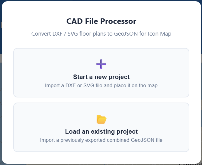
1. Start a project
- Open Tools -> CAD File Processor
- Choose Start a new project to import a
DXForSVG - Or choose Load an existing project to reopen a previously exported Combined GeoJSON
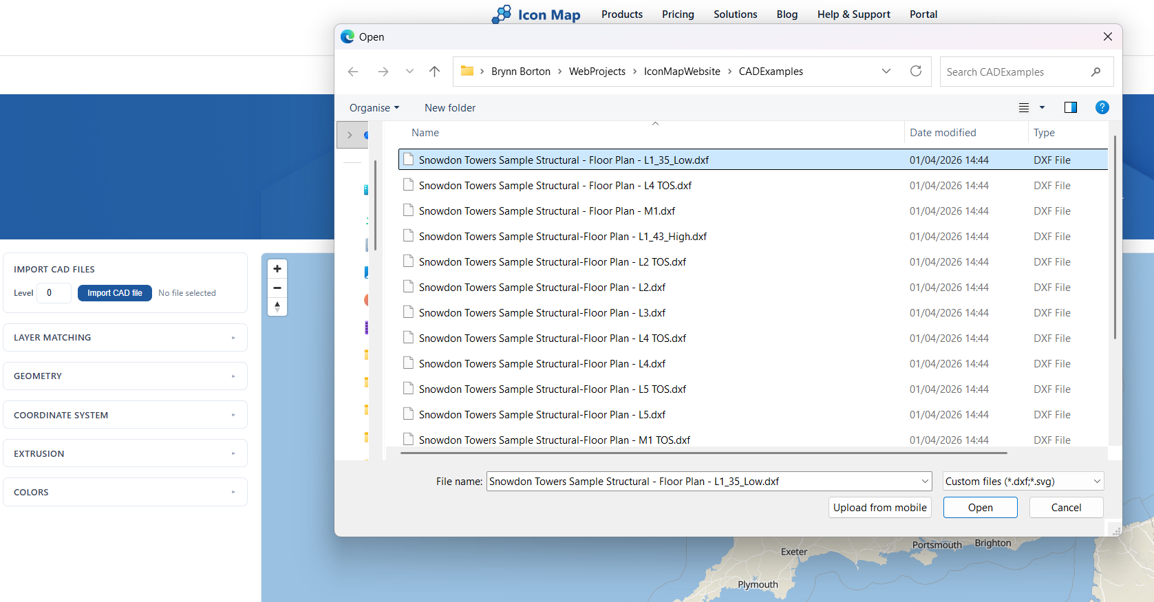
2. Import your DXF or SVG
- Set the Level value before import
- Click Import CAD file
- Select a
DXForSVGfile - Review the detected CAD/SVG layers in the layer list
The Level value is important for multi-floor buildings. Each import is stamped with that level, and the tool will keep levels separate so you can build up a full multi-storey plan one floor at a time.
If you re-import a drawing into the same level later, that level is replaced while other levels are kept.
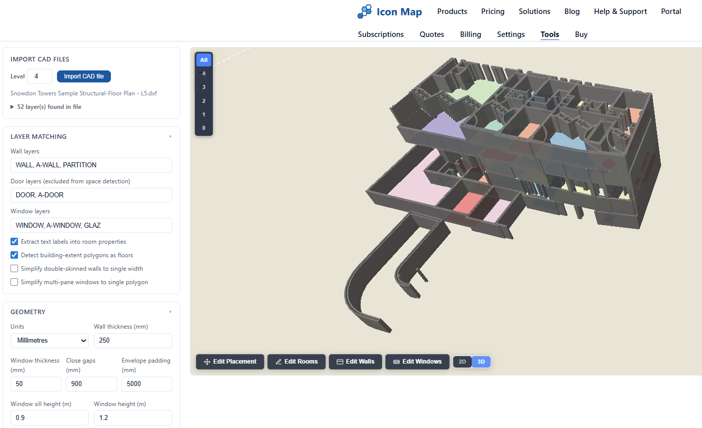
3. Review the import settings
Before or after your first import, review the settings in the left-hand panel.
Layer matching
Use Layer matching to tell the tool which CAD layers represent:
- Wall layers
- Door layers
- Window layers
These are matched using layer-name patterns, so you can adapt the defaults to your own CAD naming conventions.
You can also enable:
- Extract text labels into room properties
- Detect building-extent polygons as floors
- Simplify double-skinned walls to single width
- Simplify multi-pane windows to single polygon
Geometry
Use Geometry to tune how the processor converts lines into polygons:
- Units:
MillimetresorMetres - Wall thickness
- Window thickness
- Close gaps
- Envelope padding
- Window sill height
- Window height
These settings matter most when walls are not perfectly closed, or when the source drawing uses centerlines rather than already-closed wall polygons.
If you import an SVG, the tool auto-calculates some geometry defaults based on the size of the drawing. You can still adjust them and reprocess.
Coordinate system
Use Coordinate system to tell the tool what coordinates are in the file:
- Local / Arbitrary: the drawing is not yet georeferenced and must be placed on the map manually
- EPSG:3857: already in Web Mercator
- EPSG:27700: already in British National Grid
If your CAD is already georeferenced, placement is skipped and the drawing is loaded directly onto the map.
Reprocess vs Update
- Use Reprocess after changing layer matching, geometry, or coordinate-system settings. This re-parses the original CAD file.
- Use Update after changing styling or extrusion settings on the processed result.
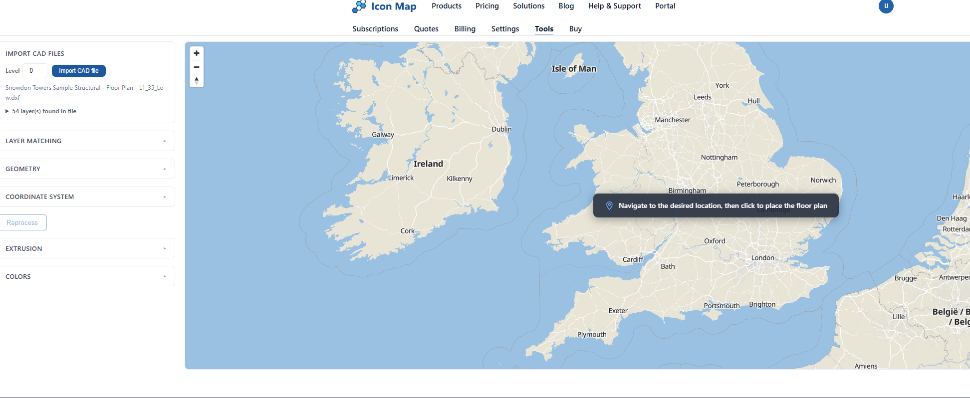
4. Place the floor plan on the real map location
If the input coordinate system is Local / Arbitrary, the tool will ask you to place the drawing.
- Pan and zoom the map to the real building location
- Click the map once to drop the plan onto that location
- Use the placement tools to align it accurately
The tool provides two placement modes:
- Drag / Scale / Rotate
- Control Points
The usual workflow is:
- Do a rough placement with Drag / Scale / Rotate
- Switch to Control Points for accurate alignment
- Click Confirm once the plan sits correctly over the building footprint
You can reopen placement later using Edit Placement.
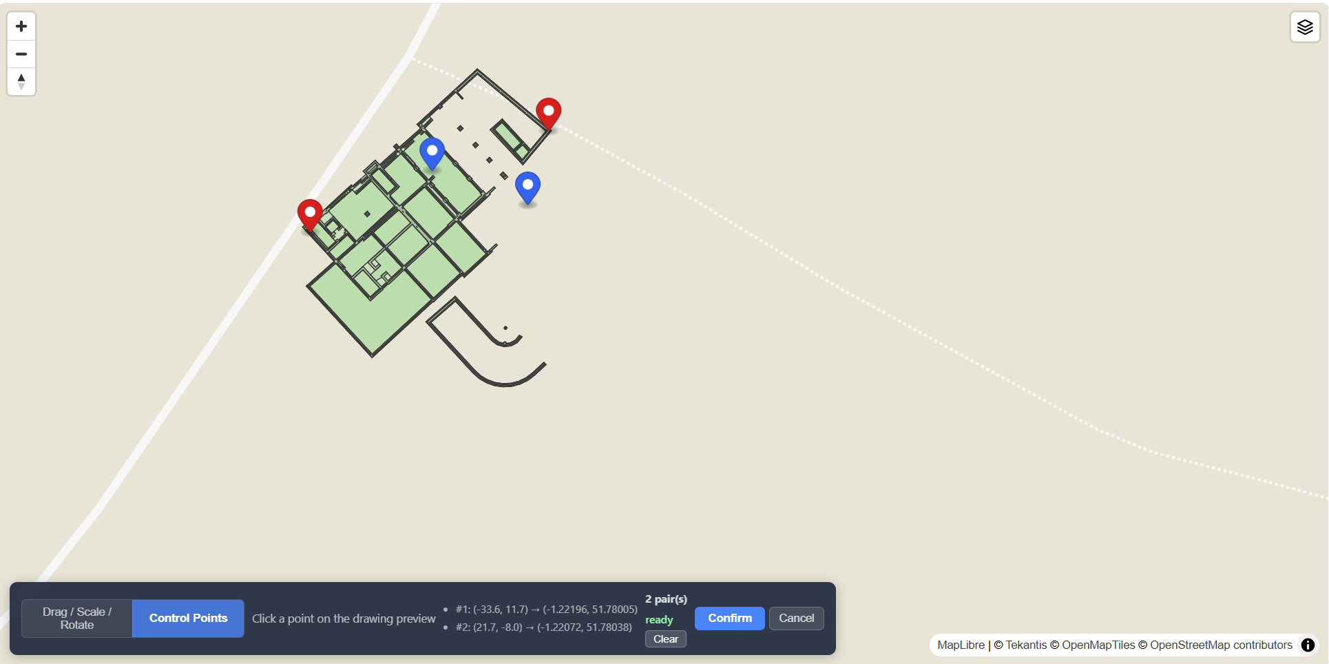
Recommended georeferencing workflow with control points
This is the best way to rotate and scale a floor plan onto the actual building.
- Place the drawing roughly on top of the building
- Switch to Control Points
- Click a known point on the drawing preview, such as a building corner
- Click the matching real-world point on the basemap
- Repeat with a second point that is as far away as possible from the first
- Add a third pair if you want to validate the fit visually
- Click Confirm
Use corners or other fixed architectural points that are easy to identify in both the plan and the map imagery.
The tool needs at least 2 control-point pairs before it can confirm.
If the map background is hard to interpret, use the background style switcher in the map controls to change the basemap style before aligning.
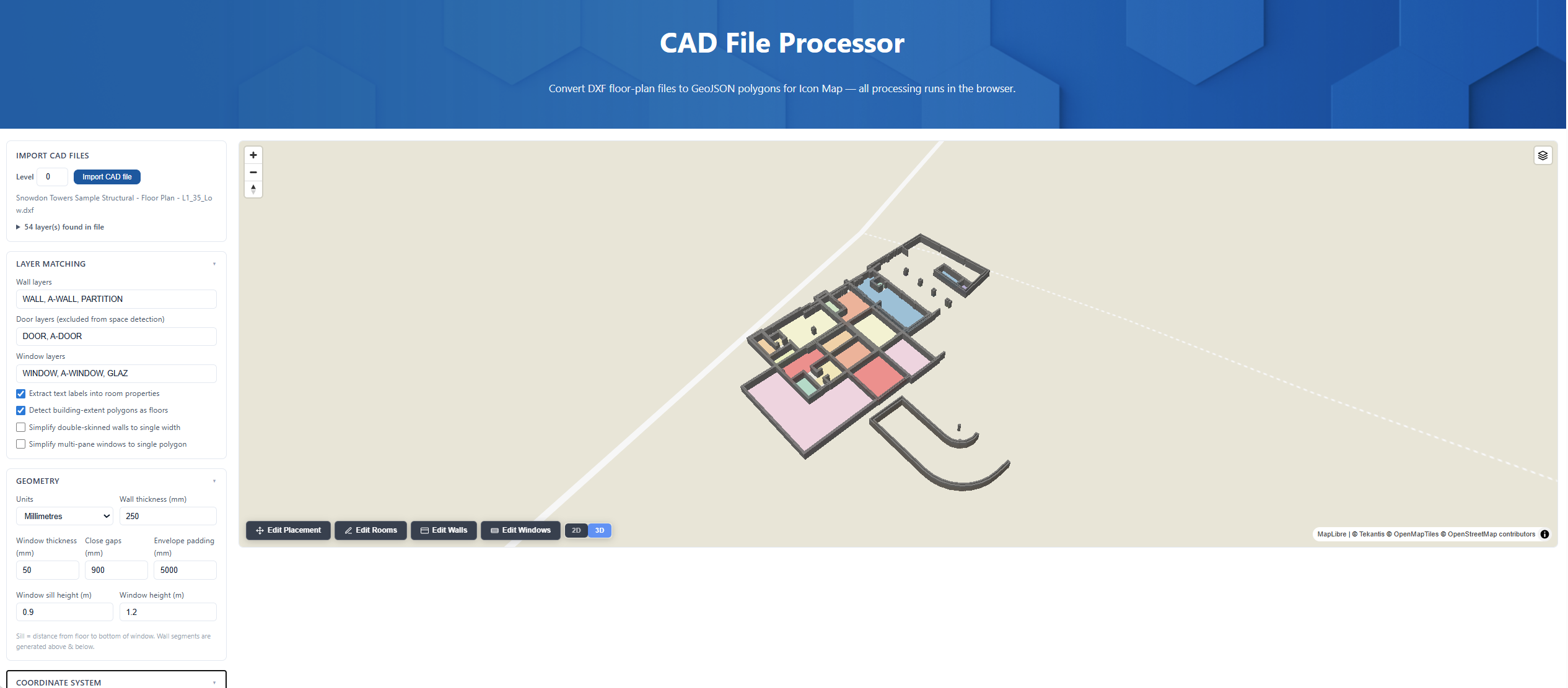
What the tool auto-detects
After processing, the tool generates GeoJSON features for the parts of the floor plan it can identify.
Walls
Walls are detected from the wall layers you define. These are converted into wall polygons ready for 2D display or 3D extrusion.
If your source plan uses paired wall lines, Simplify double-skinned walls to single width can help turn those into cleaner wall shapes.
Rooms
Enclosed spaces are detected automatically as room polygons. In the exported data these are stored as space features.
Each room is given identifiers such as:
space_ididlevel
If Extract text labels into room properties is enabled, text found in or near rooms is added into the room properties, giving you a useful starting point for labels such as room names, numbers, or codes.
Floors
If Detect building-extent polygons as floors is enabled, the tool will create floor features for the overall building footprint or floor extent where it can infer them.
Windows
Windows are detected from the window layers and turned into window features. The processor also creates matching wall sections above and below the opening, based on the configured sill height and window height.
Manually editing the result
The processor is not limited to fully automatic output. Once the drawing is placed, you can clean up the result directly on the map.
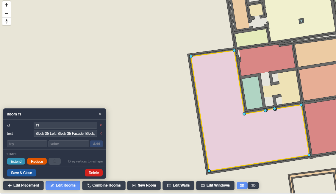
Room editing
Click Edit Rooms to work with room polygons.
You can:
- click a room to edit its properties
- drag room vertices to reshape the boundary
- add custom room properties
- remove room properties
- create a New Room
- Combine Rooms
- Extend a room by drawing an added polygon
- Reduce a room by drawing a cut polygon
- Delete a room
- Undo the last room edit
This is useful when room detection is almost correct but needs manual cleanup around lobbies, split rooms, merged rooms, or irregular shapes.
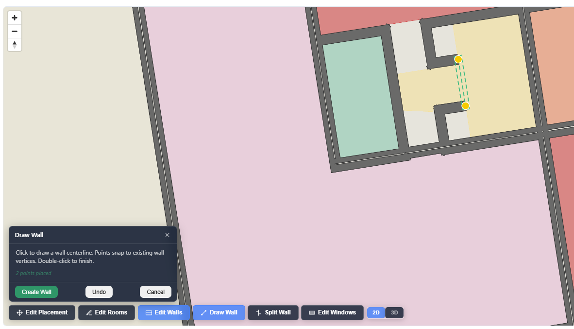
Wall editing
Click Edit Walls to adjust wall geometry.
You can:
- drag wall corner points to reshape existing walls
- use Draw Wall to add a new wall segment
- use Split Wall to cut an existing wall with a drawn line
- use Undo to step back the last wall edit
This is useful when the import misses a wall segment, when a wall needs extending, or when a single detected wall should really be split into smaller sections.
Window editing
Click Edit Windows to adjust window openings.
You can:
- click a window to select it
- drag its blue vertices to reshape it
- use Add Window to draw a new window opening
- change Sill height
- change Window height
- Delete a window
- Undo the last window edit
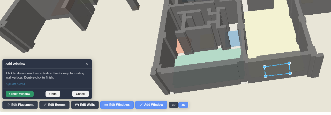
2D and 3D views
Use the 2D / 3D toggle to inspect the result:
- 2D is best for editing geometry
- 3D is best for checking wall height, floor position, and window openings
For multi-level projects, use the level picker on the map to show a single level or All levels together.
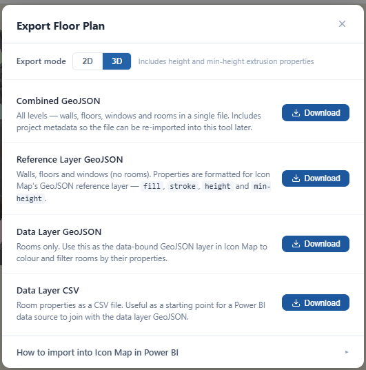
Exporting the result
Click Download GeoJSON to open the export dialog.
You can export in either:
- 2D
- 3D
In 3D mode the exported GeoJSON includes extrusion properties such as height and min-height. In 2D mode it exports flat polygons only.
The export dialog provides four outputs:
Combined GeoJSON
This contains:
- all levels
- walls
- floors
- windows
- rooms
- saved processor settings and metadata
Use this when you want to save your work and reopen it later in the CAD File Processor.
Reference Layer GeoJSON
This contains:
- walls
- floors
- windows
It does not include rooms.
Use this as the floor-plan reference layer in Icon Map.
Data Layer GeoJSON
This contains:
- room polygons only
Use this when you want rooms to behave as a data-driven layer in Icon Map, for example to color rooms by occupancy, category, department, risk, or any other property.
Data Layer CSV
This exports the room properties as a CSV table. It is useful as a starter dataset for Power BI or for joining room attributes later.
Loading the exports into Icon Map Slicer
There are two common ways to use the output in Icon Map Slicer.
Option 1: GeoJSON file import
Use this when you want to upload the exported GeoJSON files directly into the visual.
- Export Reference Layer GeoJSON if you want the building shell, walls, floors, and windows as a map layer
- Export Data Layer GeoJSON if you want room polygons as a separate GeoJSON layer
- In Power BI, follow the file-based import workflow in GeoJSON / Shapefile / KML (from file)
Typical pattern:
- use Reference Layer GeoJSON for the static building geometry
- use Data Layer GeoJSON when you want file-based room polygons that can be joined to your data
Option 2: Shapes from data (WKT / GeoJSON in your model)
Use this when you want the room shapes stored in your database or semantic model rather than in an uploaded file.
- Export Data Layer GeoJSON
- Load those room geometries into your data source as GeoJSON features, or convert them to WKT in your ETL/database process if that suits your model better
- Use Data Layer CSV as a helpful starter table for room attributes
- Follow the workflow in Working with shapes from databases (WKT / GeoJSON)
Useful join fields from the CAD processor output include:
idspace_idlevellevel_numeric- any custom room properties you add in the editor
Tips for best results
- Use CAD files with clear wall, door, and window layers where possible
- Start with the correct Units
- If rooms are missing, review Wall layers, Door layers, Wall thickness, and Close gaps, then Reprocess
- Use two control points that are far apart for better rotation and scale alignment
- Save a Combined GeoJSON regularly so you can reopen the exact working state later
- Import each floor at the correct Level so the 3D stacking works properly